
Oil Seals & Shaft Seals
Rotary lip seals that keep fluid in and contamination out — custom dimensions, any profile, any elastomer.
Overview
Essential components for moving mechanical systems
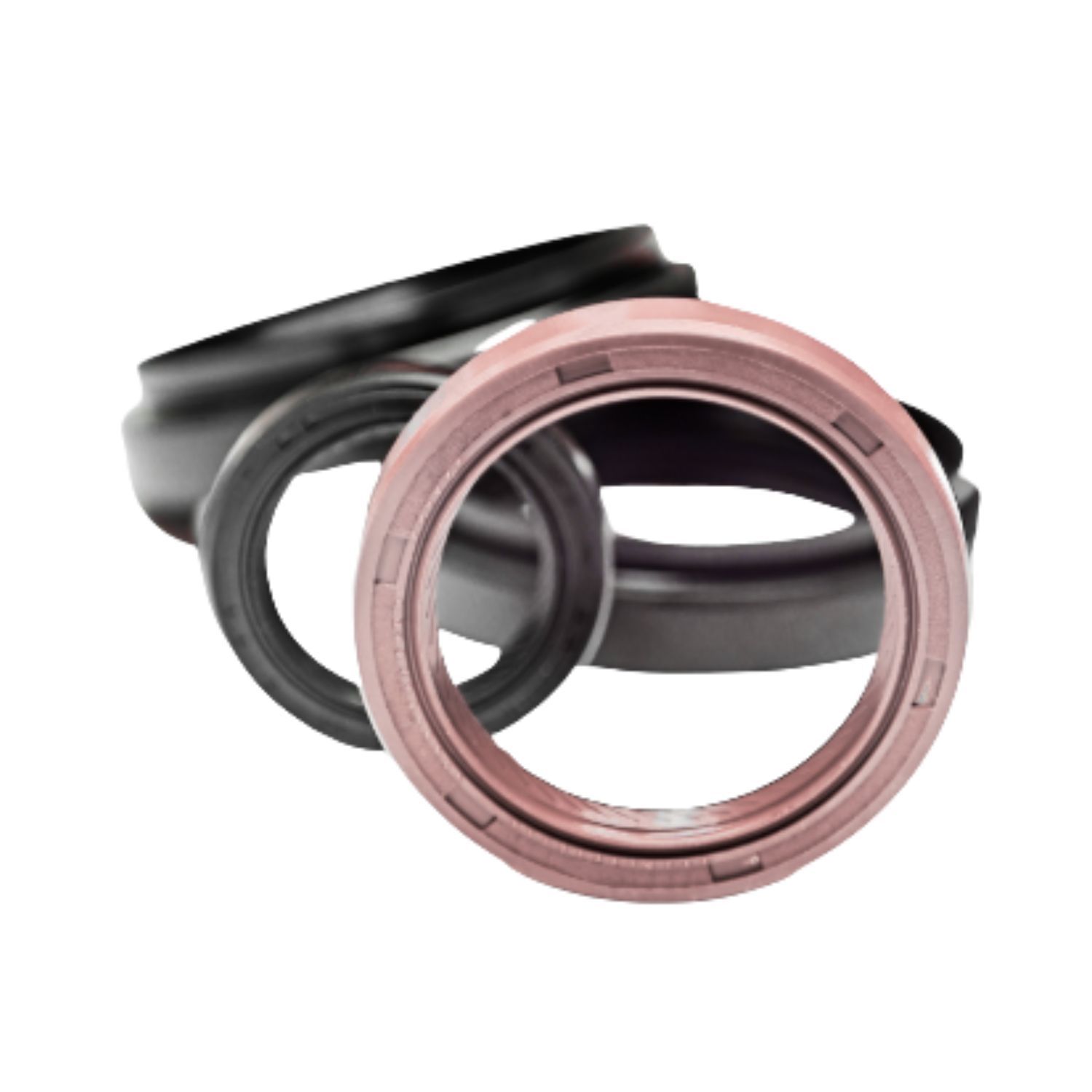
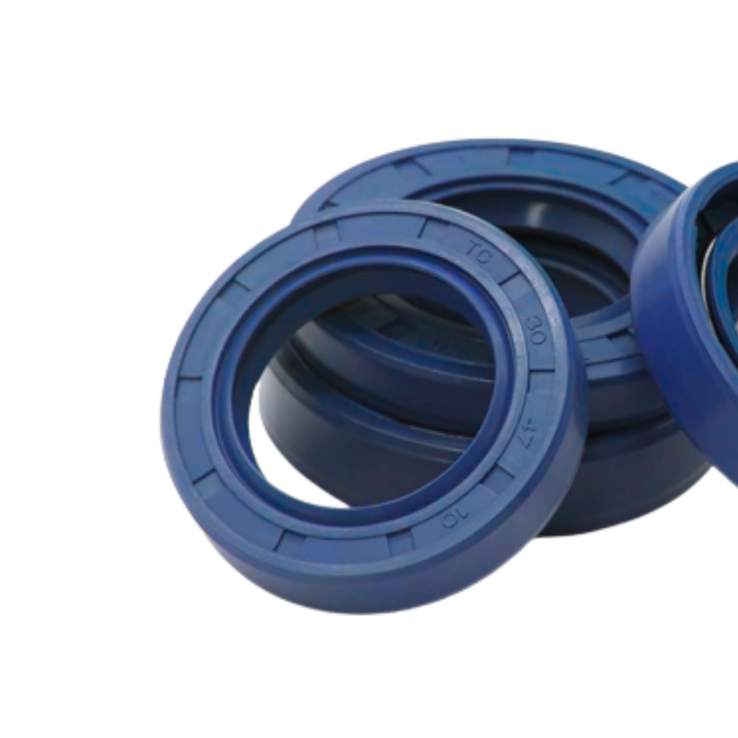
Oil seals (also called shaft seals or lip seals) are radial sealing elements that prevent fluid leakage at rotating shaft penetrations while simultaneously excluding contaminants from the bearing housing. They are found in virtually every piece of rotating equipment — automotive drivelines, industrial gearboxes, pumps, motors, agricultural machinery, and hydraulic cylinders.
The sealing action comes from a flexible lip maintained in contact with the rotating shaft by a garter spring. The lip is manufactured to an interference fit on the shaft — the exact interference determines both the sealing effectiveness and the friction heat generated. Get either the shaft finish or the interference wrong and the seal will fail prematurely, regardless of material quality.
We supply custom-made oil seals in all standard profiles and dimensions — metric and imperial, single and double lip, with and without dust exclusion lips. Standard sizes, modified dimensions, and non-standard profiles are all available.
Selection Framework
STAMP — five parameters that determine the right seal
Oil seal failures are almost always the result of a wrong material or profile selection. Running through STAMP before ordering eliminates the most common causes of premature failure.

S — Shaft diameter and surface condition
Shaft diameter determines the seal size. But equally important is shaft surface condition — it is the most common cause of seal failure in the field.
| Parameter | Requirement | Effect of Non-Conformance |
|---|---|---|
| Surface finish (Ra) | 0.2–0.8 µm (8–32 µin) | Too rough: abrasive wear of the lip. Too smooth: hydrodynamic lift — seal pumps fluid out instead of retaining it. |
| Shaft hardness | Minimum 45 HRC for PTFE lip; 30 HRC for elastomeric lip | Soft shaft surface wears a groove under the seal lip. Once a groove forms, the seal leaks regardless of replacement — shaft must be repaired first. |
| Shaft lead / helix | No machining lead (ground or polished surface) | Machining marks that spiral along the shaft act as a pump, forcing fluid past the lip regardless of sealing contact. |
| Runout / eccentricity | Max 0.25 mm TIR at operating speed | Excessive runout causes the lip to lift repeatedly, allowing fluid escape and accelerating lip fatigue. |
T — Temperature range
| Material | Continuous Range | Notes |
|---|---|---|
| NBR (Nitrile) | –40°C to +100°C | Standard material. Adequate for the majority of mineral oil applications. |
| HNBR | –40°C to +150°C | Hydrogenated NBR — improved heat, ozone, and chemical resistance over standard NBR. |
| FKM (Viton®) | –20°C to +200°C | Required for elevated temperatures and synthetic lubricants. Best overall chemical resistance. |
| PTFE | –60°C to +220°C | Widest temperature range. No spring required in some designs. Requires harder, smoother shaft. |
| Silicone (VMQ) | –60°C to +200°C | Cold-start advantage. Lower mechanical strength — not suitable for dynamic abrasion or high shaft speeds. |
| EPDM | –50°C to +150°C | Required for water/steam service and brake fluid. Incompatible with mineral oils. |
A — Application type & M — Shaft speed
| Application | Max. Shaft Speed | Considerations |
|---|---|---|
| Standard radial lip seal | Up to 4–6 m/s | Standard application range. Single lip with garter spring. Elastomeric material matched to fluid. |
| PTFE lip seal | Up to 15 m/s | Lower friction and better heat dissipation than elastomeric at high speed. Requires better shaft finish. |
| Double lip seal | Same as single lip | Secondary dust lip for contamination exclusion in dirty environments. Adds friction — account for heat. |
| Cassette seal | High-speed, high-contamination | Multi-lip metal-cased assembly. For extreme contamination — see Cassette Seals page. |
P — Operating pressure
Standard radial lip seals are designed for low-pressure differential — they are not pressure seals.
| Pressure Condition | Seal Type Required |
|---|---|
| 0–0.3 bar differential | Standard radial lip seal — no modification needed |
| 0.3–3 bar | Reinforced lip or pressure lip seal design — consult application |
| >3 bar | Hydraulic rod seal or specialized rotary pressure seal — oil seals are not appropriate |
Running a standard oil seal under pressure reverses the lip geometry, causing rapid extrusion and failure. This is a very common failure mode when a gearbox or bearing housing is inadvertently pressurized.
Materials
Lip material selection
NBR (Nitrile)
HNBR
FKM (Viton®)
PTFE
Silicone (VMQ)
EPDM
Troubleshooting
Oil seal failure analysis
Most oil seal failures are predictable and preventable. The table below covers the six most common failure modes, their root causes, and the corrective action. If the same seal fails repeatedly after replacement, the answer is in this table — not in a different brand of seal.
Leakage at the sealing lip
| Probable Cause | Corrective Action |
|---|---|
| Shaft surface too rough | Re-finish shaft to Ra 0.2–0.8 µm. Grinding marks must not spiral — use plunge grinding or superfinishing. |
| Shaft surface too smooth (below Ra 0.2 µm) | The lip hydroplanes on the oil film and pumps fluid outward. Re-grind to target Ra range. |
| Machining lead on shaft | Spiral tool marks act as a pump thread. Replace shaft or use a seal with a reverse hydrodynamic lip feature. |
| Garter spring missing or broken | Inspect spring. Never re-use a spring from a failed seal. Verify spring is correctly seated in the lip groove. |
| Seal installed backwards | Verify lip orientation — sealing lip must face the oil side (inward). Dust lip, if present, faces outward. |
| Incorrect material — lip hardened by fluid | Check fluid compatibility chart. Swell or hardening indicates chemical incompatibility — upgrade material grade. |
Leakage on the outer circumference (OD)
| Probable Cause | Corrective Action |
|---|---|
| OD damaged during installation | Use proper installation tool (sleeve or driver matching OD). Never tap directly on the seal case with a hammer. |
| Housing bore oversized or out of round | Measure bore against seal OD specification. Bore must be within tolerance and within 0.025 mm roundness. |
| Housing bore surface too rough | Bore finish must be Ra 1.6–3.2 µm. Use a bonded seal (rubber OD) instead of a metal OD seal in rough bores. |
| Seal OD undersized (wrong part) | Verify part number. An oil seal that requires no effort to press into bore is the wrong size. |
Sealing lip turned back / inverted
| Probable Cause | Corrective Action |
|---|---|
| Back pressure in housing | Standard lip seals are not pressure seals. A pressurized bearing housing reverses the lip. Add a vent or drain to relieve back pressure, or specify a pressure-rated seal design. |
| Lip folded during installation | Use correct installation sleeve. Inspect the lip before pressing into housing. Any folding during installation will cause immediate failure. |
Abnormal wear / accelerated seal life
| Probable Cause | Corrective Action |
|---|---|
| Shaft runout exceeds 0.25 mm TIR | Check shaft straightness, bearing condition, and coupling alignment. Runout causes the lip to alternately lift and slam against the shaft — fatigue failure. |
| Abrasive contamination in fluid | Metallic particles or abrasive debris in the oil act as lapping compound at the lip contact zone. Investigate fluid contamination source. Consider adding a V-ring or cassette seal as an exclusion barrier. |
| Operating temperature too high | Elevated temperature hardens the lip and accelerates wear. Check actual sump temperature — it is often higher than expected. Upgrade to HNBR or FKM if NBR is at its thermal limit. |
| Shaft speed exceeds seal rating | Verify seal speed rating against actual shaft speed. Consider PTFE lip seal above 6 m/s shaft surface speed. |
Lip hardening, cracking, or permanent compression set
| Probable Cause | Corrective Action |
|---|---|
| Fluid incompatibility | Certain fluids (synthetic lubricants, EP additives, solvents) attack NBR. Inspect the removed seal — if the lip is hard and brittle, it's a material issue. Cross-reference fluid with elastomer compatibility chart. |
| Sustained overtemperature | Heat accelerates elastomer aging irreversibly. Lip hardens and loses contact force. Investigate thermal source — over-filled housing, blocked ventilation, bearing overload, or wrong lubricant viscosity. |
| Long storage without lubrication | Seals stored dry under static compression (on a shaft during a long shutdown) develop permanent set at the lip contact zone. Rotate machinery periodically during extended shutdowns. Lubricate shaft contact area before restarting. |
Groove / score marks on shaft at seal contact zone
| Probable Cause | Corrective Action |
|---|---|
| Hard particles in fluid acting as abrasive | Address contamination source. A scored shaft will cause every replacement seal to leak — the shaft must be repaired before the seal is replaced. Options: weld and re-grind, install a speedi-sleeve (repair sleeve), or relocate seal on shaft if geometry permits. |
| Shaft too soft (hardness below 30 HRC) | The seal lip gradually abrades a groove into a soft shaft. Minimum shaft hardness: 30 HRC for elastomeric lip seals, 45 HRC for PTFE. Repair or replace shaft; do not simply replace the seal. |
A replacement seal installed over a worn groove will leak immediately. There is no seal material or brand that seals against a shaft groove — the shaft must be repaired first.
Need oil seals for your application?
Provide shaft diameter, housing bore, shaft speed, temperature, and fluid — we'll specify the right material and profile and source to your dimensions.
Request a Quote