
Quad-Rings (X-Rings) & Square Rings
Three cross-section geometries beyond the round O-ring — each solving a specific problem the standard round seal cannot.
Overview
When the round cross-section isn't the right answer
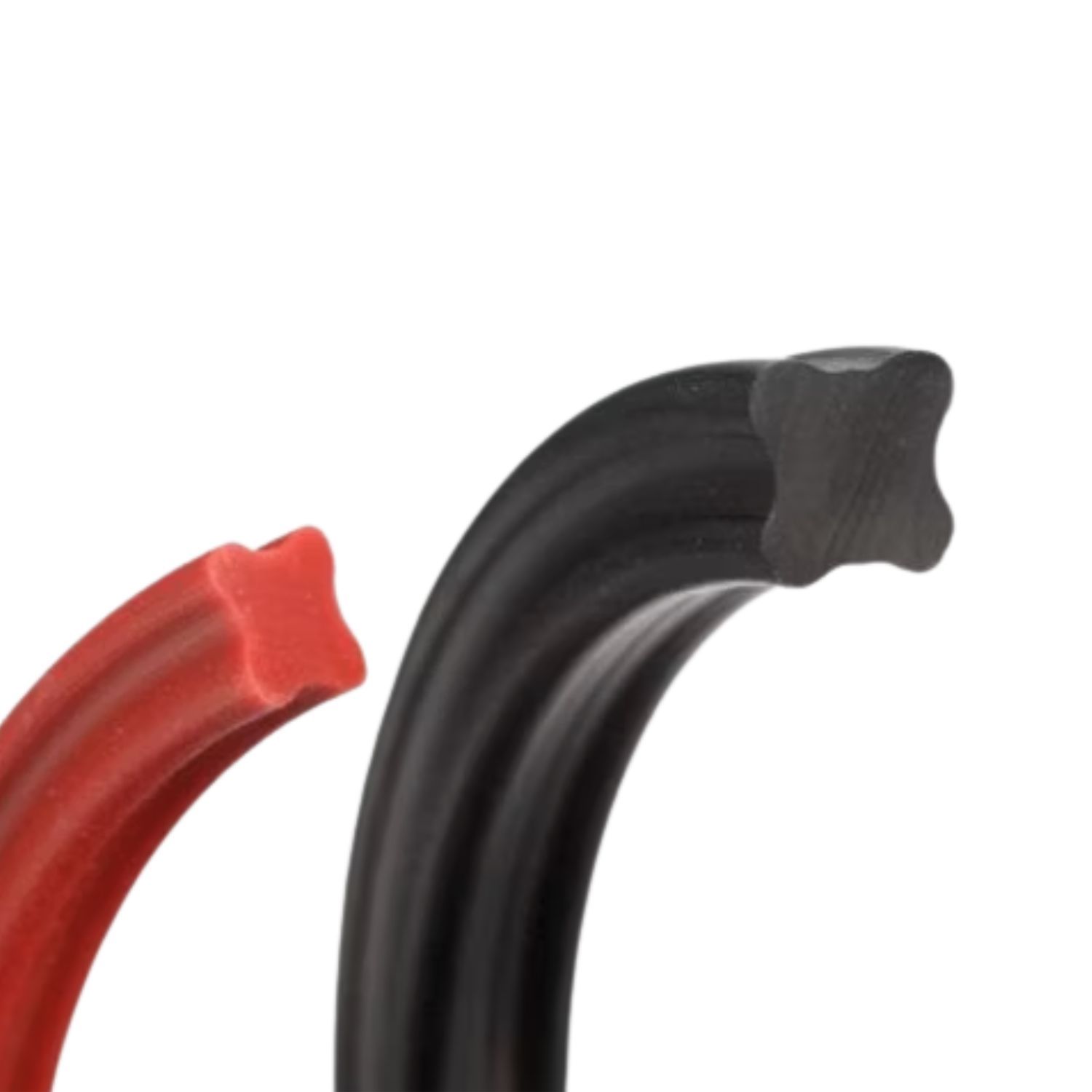
The O-ring is the standard — self-energizing, versatile, and proven across decades of industrial service. But two cross-section geometries address failure modes the round O-ring cannot resolve on its own: the X-ring (quad-ring) eliminates spiral failure and cuts friction in reciprocating dynamic service, and the square ring delivers a broader, more uniform sealing footprint for static face seals and surfaces that carry minor imperfections.
The X-ring fits standard O-ring grooves without modification. The four-lobe cross-section creates four sealing contact points instead of two, retains lubricant between strokes, and locks position in the groove to prevent the rolling failure that accounts for a significant share of cylinder seal replacements.
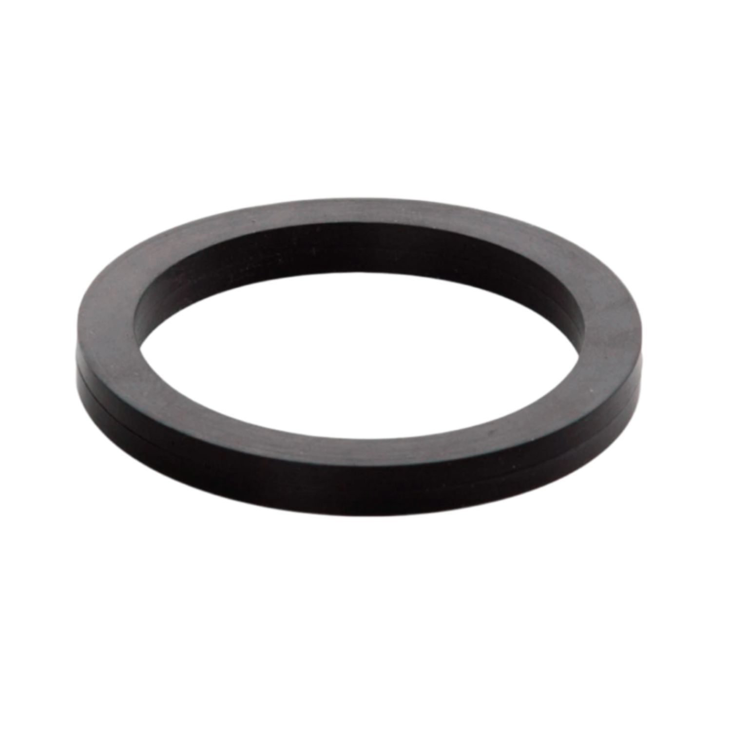
The square ring sits flat in the groove on two wide faces. At ELASFOR, we favour the square ring for 2-piece assemblies and face seals where uniform load distribution matters more than self-energization — and for any surface where machining marks, porosity, or minor casting imperfections require a wider sealing contact band to achieve a reliable static seal.
Design Reference
Selection & installation guidance
X-ring vs O-ring — head-to-head
X-rings are not a universal replacement for O-rings — they excel in dynamic applications where friction and spiral failure are the operative failure modes. In low-pressure static seals with no motion, a standard O-ring is equally effective and costs less.
| Characteristic | O-ring | X-ring (Quad-ring) | Practical Impact |
|---|---|---|---|
| Sealing contact points | 2 (top & bottom) | 4 (dual lobe per surface) | X-ring seals at lower compression — more margin against manufacturing tolerance variation. |
| Spiral (screw) failure | Possible in reciprocating service | Eliminated by lobe geometry | Most important advantage in hydraulic and pneumatic cylinders with mixed or irregular stroke motion. |
| Friction (dynamic) | Baseline | 20–50% lower | Lobe channels retain lubricant film between strokes. Critical in pneumatic tools and medical devices where lubrication is minimal. |
| Groove required | Standard O-ring groove | Same standard O-ring groove | Direct drop-in — no machining, no redesign. Use the existing gland dimensions. |
| Cost premium | Baseline | Moderate (10–30% higher) | Often offset at first maintenance cycle: fewer replacements and reduced cylinder wear. |
Groove dimensions & compression ratio
X-rings use the same groove geometry as standard O-rings — groove width, groove depth, surface finish, and lead-in chamfer requirements are identical. The compression ratio targets differ slightly: the four-contact geometry seals effectively at lower squeeze percentages, which is a direct advantage in dynamic service.

| Application | Recommended Compression | Notes |
|---|---|---|
| Static — face / radial | 10 % – 20 % | Lower end of the O-ring static range is sufficient due to dual contact per sealing surface. Do not over-compress. |
| Dynamic — reciprocating | 7 % – 14 % | Primary use case for X-rings. Less compression = less friction = less heat generation. Compatible with existing O-ring glands designed for 10–16% squeeze. |
| Dynamic — oscillating | 8 % – 15 % | Rotary or oscillating shafts: X-ring lobe channels maintain lubricant film through direction change. Advantage over O-ring greatest at low shaft speeds. |
Groove dimensions per AS568, BS1806, and ISO 3601. Use the same gland calculator as for O-rings — no adjustment required for cross-section size.
Spiral failure — the hidden failure mode X-rings eliminate
Spiral failure happens when an O-ring rolls in its groove under reciprocating motion. The round cross-section has no resistance to rotation — particularly on slow or irregular strokes where friction is uneven across the seal circumference. The seal twists 90°, creating a helical path and a continuous leak channel that looks like an extrusion nick on inspection.

| Factor | Effect on Spiral Risk | X-ring Solution |
|---|---|---|
| Slow or variable stroke speed | Highest risk — friction builds unevenly across seal circumference | Lobe geometry resists rotation mechanically. No dependence on speed or lubrication uniformity. |
| Insufficient lubrication | Increases friction differential — one side of seal grabs while other slides | Lobe channels retain lubricant between strokes, reducing the friction differential that initiates rolling. |
| Eccentric load or side-loading | Uneven groove contact → rolling initiation point | Four-lobe contact distributes load, reducing single-point pressure concentration. |
| Worn or oversized groove | Excess clearance increases mobility of the seal in the groove | Lobe tips maintain groove contact — more stable in worn glands than a round section. Not a substitute for a properly dimensioned groove. |
Installation requirements
Installation requirements are identical to O-rings. The lobe geometry does not require special tools, but one step matters more than with O-rings: lubrication at assembly. The lobe channels need to be pre-filled with lubricant — if installed dry, the channels provide no benefit and initial friction is higher than an O-ring until the system lubricant wets the seal.

| Step | Requirement | Notes |
|---|---|---|
| Groove inspection | No burrs, sharp edges, or corrosion pitting on groove walls or bore | Same standard as O-ring installation. Edge radius 0.2–0.4 mm minimum on all seal contact edges. |
| Lubrication | Coat all four lobes generously with system fluid or compatible grease before installation | More critical than for O-rings — the lobe channels must be filled to function. Use silicone grease for pneumatic/dry service; system hydraulic fluid elsewhere. |
| Orientation check | X-rings are symmetric — any orientation is correct | Verify the seal is seated flat in the groove, not twisted. A twisted X-ring at installation will not untwist in service. |
| Shaft / bore lead-in | 15°–20° chamfer, minimum length = 1× cross-section diameter | Same as O-ring. Never force an X-ring over a sharp thread or keyway — use a mandrel or installation cone. |
Square Rings
Where ELASFOR recommends square over round
A square ring has the same outside diameter and fits the same groove as an equivalent O-ring, but the cross-section is square rather than round. That geometry shift changes the contact mechanics entirely: instead of two narrow curved sealing lines, you get two wide flat sealing bands — one against the groove floor, one against the mating face. More surface in contact means more uniform load distribution and better tolerance of surface imperfections.
Where square rings outperform — ELASFOR's preferred applications
The square ring is our first recommendation in two scenarios: 2-piece face seal assemblies where bolt load variation can create uneven contact stress across a round seal, and mating surfaces that carry minor asperities, machining marks, or casting porosity that an O-ring's narrow contact arc cannot fully bridge.
| Criterion | O-ring (round) | Square Ring | Why It Matters |
|---|---|---|---|
| Sealing contact width | Narrow arc — high unit pressure at two contact lines | Wide flat band — uniform pressure across the full contact width | Wide contact bridges surface asperities and minor machining imperfections. Narrow contact concentrates stress but requires a cleaner surface. |
| 2-piece face seal stability | Round section can shift laterally under uneven bolt loading | Flat bottom sits stable in the groove under any bolt torque pattern | Critical in flanged assemblies where bolt spacing or torquing sequence creates non-uniform compression across the seal. |
| Groove stability (static) | Round section can roll if groove tolerances are loose | Flat faces lock against groove walls — no rolling possible | In face seals that see vibration or thermal cycling without pressure, the square ring stays put where a round section can migrate. |
| Surface conformance | Line contact — does not span rough or irregular surfaces well | Flat sealing face distributes over a wider band — more forgiving of surface condition | As-cast surfaces, rough flanges, or worn mating faces that would leak past a round O-ring often seal reliably with a square ring of the same groove dimensions. |
| Assembly in a 2-pc seal | Round section may be pinched or displaced during assembly if alignment is imperfect | Square profile is more resistant to being pinched or rolled out of position during assembly | Reduces assembly errors on large-bore or complex-geometry face seals where the seal is difficult to observe during closure. |
Square ring limitations — and why the O-ring is still the reference seal
The square ring is not a universal replacement for the O-ring. Its flat geometry creates real tradeoffs that disqualify it from dynamic service and from applications where the self-energizing behaviour of a round cross-section is doing the work. We call these out plainly so the right seal goes into the right application.
| Limitation | Detail | When It Matters |
|---|---|---|
| Not self-energizing | The O-ring's round cross-section rolls under system pressure, concentrating sealing force at the contact lines in proportion to pressure. A square ring distributes pressure uniformly but does not amplify it. | At low system pressures (< 10 bar), the square ring relies entirely on mechanical compression for sealing. The O-ring gains sealing force from system pressure — making it more reliable in low-pressure and vacuum service. |
| Not for dynamic service | The flat face creates significantly higher friction against bore or shaft than a round or quad-lobe cross-section. Heat generation in dynamic service leads to rapid wear and compression set. | Square rings are static seals only. In any reciprocating, rotary, or oscillating application, use an O-ring or X-ring. |
| Higher compression set risk | The full flat contact face is always in compression — there is no geometric recovery mechanism. Over long service intervals, compression set reduces sealing force faster than with a round section. | For seals that must hold for years between maintenance cycles at elevated temperature, a properly specified O-ring outlasts the square ring. The round section self-corrects to some extent as it rolls under pressure load. |
| Less forgiving groove design | Groove width must match the square cross-section precisely. Too wide and the ring tilts; too narrow and it cannot seat flat. The O-ring's round profile is more tolerant of minor groove width variation. | Retrofit applications where groove dimensions are fixed should verify that the square ring cross-section matches the groove width within tolerance before switching. |
Bottom line: for long-term static sealing under sustained pressure, the O-ring with a properly designed groove and appropriate compound remains the superior engineered solution. The square ring solves specific problems — face seal stability, surface conformance, 2-piece assembly reliability — and should be specified for those problems, not as a general replacement.
Material Quick Reference
Available compounds — quad-rings (X-rings) & square rings
All three cross-section geometries are available in the same compound families. Material selection follows the same chemical compatibility and temperature criteria as O-rings — the geometry does not change fluid compatibility. Urethane is particularly relevant for X-rings in mobile hydraulics; for square rings in face seal service, NBR and FKM cover the majority of applications.
NBR — Nitrile
−40 °C to +120 °C · 70 Shore A standard
Petroleum oils, hydraulic fluids, fuels, water-glycol. Default choice for industrial hydraulic and pneumatic cylinders.
Urethane (AU/PU)
−40 °C to +100 °C · 70–95 Shore A
Exceptional abrasion resistance and mechanical strength. Popular in mobile hydraulics, linear guides, and high-cycle pneumatic actuators where groove and bore wear are the failure mode. Not suitable for hot water, steam, or strong acids/bases.
FKM — Fluorocarbon (Viton)
−20 °C to +200 °C · 70–80 Shore A
Aggressive chemicals, fuels, high-temperature hydraulic fluid. Where NBR degrades, FKM holds.
EPDM
−55 °C to +150 °C · 70 Shore A standard
Steam, hot water, brake fluids, phosphate-ester hydraulics (Skydrol). Not compatible with petroleum oils.
Silicone (VMQ)
−60 °C to +200 °C · 50–70 Shore A
Low-friction pneumatic service, food contact, medical devices, extreme temperature cycling. Low tensile strength — avoid high dynamic loads.
Need quad-rings (X-rings) or square rings?
Tell us the cross-section, inner diameter, material, and application — static or dynamic, face seal or bore seal. We'll recommend the right geometry and come back with a solution.
Request a quote