
O-rings & Back-up Rings
The most versatile sealing solution in industry — and the anti-extrusion ring that lets it work at the pressures your application actually runs.

Overview
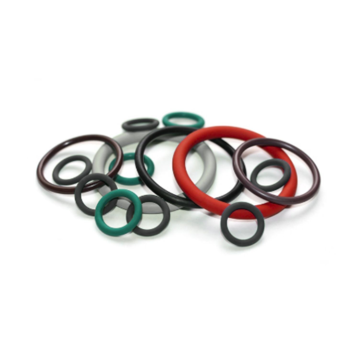
The gold standard in sealing
O-rings are found in countless industrial applications. Many remember the faulty O-ring that contributed to the crisis during the Apollo 13 mission — but their reliability in every other system on board is what brought the crew home safely. That's the real story of O-ring engineering.
Their circular cross-section and elasticity create a barrier between two surfaces, preventing leaks of liquids or gases even under extreme pressures and temperatures. Made from nitrile (NBR), silicone (VMQ), fluorocarbon (FKM/Viton), EPDM, HNBR, and more, O-rings adapt to conditions ranging from corrosive chemical environments to deep-freeze cold storage.
At ELASFOR, we supply O-rings in every conceivable size and material — stock and custom. Unusual bore? Metric groove in an imperial world? Specific compound for a fluid your regular supplier can't identify? That's where we come in.
Design Reference
Groove & installation design
Groove dimensions
These are the baseline rules that give an O-ring enough room to function — too tight and it extrudes, too loose and it rolls. Get these four parameters right and the rest follows.

| Parameter | Key Design Rule | Why It Matters |
|---|---|---|
| Groove Width (b) | Must exceed groove depth (h). Rule of thumb: ×1.35 relative to the O-ring cross-section diameter. | Elastomers are incompressible — the displaced volume must go somewhere. Without lateral room the seal over-stresses and cracks. |
| Groove Volume | Must be at least 15% greater than the O-ring volume. | Prevents hydraulic locking during installation and stops thermal expansion from destroying the seal at temperature. |
| Groove Depth (h) | Sets the compression ratio — sized against the O-ring cross-section for the target squeeze percentage. | Under-depth = leak. Over-depth = extrusion under pressure. See Compression Ratio table below. |
| Radial Clearance | Minimize the gap between mating parts. Maximum allowable gap is a function of pressure and Shore hardness. | Too much clearance allows cold-flow or extrusion into the gap under pressure cycling — nibbling failure. Back-up rings fix large clearances. |
Detailed gland dimension tables per AS568, BS1806, and metric standards available on request.
Compression ratio (squeeze / deflection)
Compression ratio is how much the O-ring cross-section is squeezed between groove depth and mating surface. Too little and you leak at low pressure; too much and you generate heat, friction, and accelerated wear in dynamic applications.

| Application Type | Recommended Squeeze | Important Notes |
|---|---|---|
| Static — face / radial | 15 % – 25 % | Above 30 % creates excessive internal stress and accelerated compression set. Higher squeeze is not always better — it just destroys the seal faster. |
| Dynamic — reciprocating | 8 % – 16 % (max 20 % for cross-sections under 1.78 mm) | Lower squeeze reduces friction, heat generation, and abrasive wear. Over-squeeze in a cylinder is the single most common cause of premature failure. |
| Dynamic — rotary shaft | 5 % – 12 % | Rotary applications generate the most heat per unit time. Consider lip seals or PTFE-encapsulated alternatives at higher RPM. |
Material selection & hardness
The O-ring must be chemically compatible with every fluid in the system — including cleaning agents and lubricants, not just the primary process fluid. Hardness (Shore A) governs extrusion resistance and friction.

| Factor | Selection Guidance | Typical Application |
|---|---|---|
| Hardness (Shore A) | Higher pressure and larger clearance gaps → harder compound (70–90 Shore A). Low-pressure static seals → softer compound (50–60 Shore A) for better surface conformance. | Hydraulic cylinders: 80–90 Shore A NBR or HNBR. Vacuum flanges: 50–60 Shore A silicone or FKM. |
| Chemical compatibility | Verify compatibility with all fluids present. Swelling >15% or hardness loss >10 points indicates incompatibility. | Petroleum hydraulics → NBR. Phosphate-ester fluids (Skydrol, HyJet) → EPDM. Aggressive solvents / high temp → FKM or FFKM. |
| Anti-extrusion rings | Required when system pressure exceeds ~100 bar (1500 psi) or radial clearance cannot be tightened. PTFE or hard nylon back-up rings fit standard grooves. | Mobile hydraulics, injection moulding clamps, wellhead equipment. |
| Temperature range | Match material limits to both operating and peak excursion temperatures. A single 30-second over-temperature event can cause permanent compression set. | −55 °C to +200 °C → FKM. −60 °C to +200 °C → Silicone. −40 °C to +150 °C → HNBR for H₂S / steam. |
Surface finish & installation
A perfect O-ring in a damaged or mis-machined groove will fail every time. Surface condition and installation technique account for a significant share of seal failures that get misdiagnosed as material selection problems.

| Element | Requirement | Installation Notes |
|---|---|---|
| Groove edges | All edges contacting the seal must be radiused — no sharp corners, no burrs. | Sharp edges are the leading cause of cut seals at assembly. A radius of 0.2–0.4 mm is sufficient. Inspect with a fingernail before installing any seal. |
| Surface finish (Ra) | Static: Ra 0.8–1.6 µm. Dynamic reciprocating: Ra 0.2–0.4 µm. Dynamic rotary: Ra 0.1–0.2 µm. | Too rough abrades the seal; too smooth can hydroplane lubricant film in dynamic applications. |
| Lead-in chamfers | 15°–20° chamfer on the entry edge of piston bores, ports, and gland covers. Length ≥ 1× O-ring cross-section. | Always lubricate the O-ring — system fluid, or compatible silicone grease for static seals. |
| ID stretch | Inner diameter stretch during installation should not exceed 50% for standard elastomers. PTFE-based O-rings have much tighter limits. | Over-stretching causes immediate micro-cracking. Use an O-ring cone or mandrel for shafts — never sharp tools. |
Material Quick Reference
Common O-ring elastomers at a glance
First-pass filter only — dozens of compound grades exist within each family. Confirm against your specific fluid and temperature profile before specifying.
NBR — Nitrile
−40 °C to +120 °C · 50–90 Shore A
Petroleum oils, hydraulic fluids, fuels, water. Default choice for most industrial hydraulics.
HNBR — Hydrogenated Nitrile
−40 °C to +150 °C · 60–90 Shore A
H₂S, amines, ozone, high-pressure hydraulics, refrigerants. Stronger and more heat-resistant than NBR.
FKM — Fluorocarbon (Viton)
−20 °C to +200 °C · 60–90 Shore A
Aggressive chemicals, fuels, high temperature. Standard choice for chemical processing and automotive.
EPDM
−55 °C to +150 °C · 40–80 Shore A
Steam, hot water, brake fluid, phosphate-ester hydraulics (Skydrol/HyJet). Incompatible with petroleum oils.
Silicone (VMQ)
−60 °C to +200 °C · 40–80 Shore A
Extreme temperature range, food and pharma, low-pressure static seals, electrical insulation.
PTFE-encapsulated
−200 °C to +260 °C · variable core
Universal chemical resistance. Used where no elastomer compound is compatible — reactors, analytical instruments, aggressive CIP/SIP.
FFKM (Kalrez / Perlast)
−25 °C to +300 °C · 65–90 Shore A
Plasma, aggressive solvents, pharmaceutical high-purity service. Highest performance and highest cost per seal.
CR — Neoprene
−40 °C to +120 °C · 40–80 Shore A
Ozone, weathering, refrigerants, moderate oils. Common in HVAC, marine, and outdoor equipment.
Back-up Rings
Anti-extrusion rings — shapes, capabilities & when to specify them
A back-up ring is a rigid or semi-rigid ring installed in the same groove as an O-ring, on the low-pressure side (single back-up) or both sides (dual back-up). Its job is to bridge the diametric clearance gap between mating parts and prevent the O-ring from cold-flowing or extruding into that gap under pressure. Without a back-up ring, that gap is the limiting factor on system pressure — with one, the O-ring operates well above what the elastomer alone could handle.
When back-up rings are required
The need for a back-up ring is determined by two factors together: system pressure and diametric clearance. Either factor alone can be acceptable — both in combination pushes the O-ring into extrusion territory. Pressure cycling is more damaging than static pressure: every cycle nibbles the seal edge a little further into the gap.
| Condition | Recommendation | Notes |
|---|---|---|
| Pressure < 100 bar, clearance ≤ 0.15 mm | No back-up ring required | Standard O-ring groove with tight machining tolerances is sufficient for most static and low-pressure dynamic applications. |
| Pressure 100–200 bar, or clearance 0.15–0.25 mm | Single back-up ring — low-pressure side of O-ring | Back-up ring prevents extrusion on the downstream side. O-ring and back-up ring share the same groove; back-up ring goes in first (toward the low-pressure side). |
| Pressure > 200 bar, or pressure cycling, or clearance > 0.25 mm | Dual back-up rings — one on each side of the O-ring | Pressure direction may reverse (hydraulic cylinders, valves). Dual back-up protects against extrusion in both directions. Required for all bidirectional high-pressure service. |
| Soft elastomers (Shore A < 60) at any pressure | Back-up ring recommended above 50 bar | Softer compounds have lower extrusion resistance. Silicone and low-durometer EPDM seals in pressure service almost always need anti-extrusion protection. |
Clearance limits are compound-dependent — a 90 Shore A NBR O-ring tolerates larger gaps than a 50 Shore A silicone at the same pressure. The values above are conservative baselines for 70 Shore A elastomers.
Solid (endless) back-up ring
One-piece continuous ring — no joint, no gap. Maximum extrusion resistance because the O-ring has zero path through which to cold-flow. Requires full disassembly to place in the groove; not usable in blind grooves without removing the shaft or piston.

| Extrusion Resistance | Installation | Best For |
|---|---|---|
| Maximum — zero gap | Full disassembly required. Shaft or piston must be removed to place ring in groove. | High-pressure static seals, piston seals assembled before bore installation, applications above 400 bar. |
Split back-up rings — scarf cut (30°) & butt cut
Both types feature a single cut across the ring cross-section that allows the ring to open and be installed without full disassembly. The scarf cut is diagonal (typically 30–45°), leaving a small helical gap under pressure. The butt cut is a straight perpendicular cut — slightly simpler to produce but leaves a straight-through gap that provides marginally less extrusion protection than the scarf. Both are the practical field choice when disassembly is not possible.

| Type | Extrusion Resistance | Installation | Best For |
|---|---|---|---|
| Scarf cut (30°) | Good — small helical gap remains. Gap size depends on ring stiffness and groove fit. | Opens and winds into groove without disassembly. PTFE scarf cuts snap into place easily. | Standard field-installable back-up ring for most hydraulic and pneumatic cylinder applications. |
| Butt cut | Good — straight-through gap slightly less favorable than scarf under pressure cycling. | Same ease of installation as scarf cut. Simpler geometry — easier to produce in harder materials. | Where scarf geometry is unavailable in the required material; lower-pressure split-ring applications. |
Spiral (multi-turn) back-up ring
A strip of PTFE wound in multiple overlapping helical turns — typically 1.5 to 2.5 turns — into the groove. No single gap runs through the full cross-section, giving extrusion resistance that approaches a solid ring while being the easiest of all types to install. Exclusively made in PTFE.

| Extrusion Resistance | Installation | Best For |
|---|---|---|
| Excellent — overlapping turns eliminate any continuous gap from face to face. | Wind the strip into the groove by hand, no tools required. Works in blind grooves and any groove geometry. | Large-bore static seals, flanges, and oversized cylinders where solid or step-cut rings are impractical. Go-to when adding a back-up ring to an existing design without modifying the groove. |
Standard back-up ring dimensions follow the same groove as the O-ring they protect. Parker, Trelleborg, and similar manufacturers publish standard groove dimension tables per AS568 and ISO 3601 for O-ring + back-up ring combinations.
Back-up Ring Materials
Anti-extrusion ring compounds at a glance
Back-up ring materials are rigid or semi-rigid — they do not seal, they support. The key properties are hardness (to resist deformation into the clearance gap), chemical compatibility with the system fluid, and enough flexibility to install into the groove without cracking. Material choice also sets the temperature ceiling and determines whether a scarf or step cut is practical.
NBR — 90 Shore A
−40 °C to +120 °C
High-hardness nitrile. Flexible enough for scarf-cut installation, hard enough to resist extrusion in petroleum hydraulic fluid service. Lowest cost and easiest to handle. Limited temperature range versus PTFE alternatives.
Urethane (AU)
−40 °C to +100 °C
Outstanding abrasion resistance and mechanical strength. Preferred in mobile hydraulics and high-cycle cylinders where the back-up ring itself can wear against the bore. Handles larger clearance gaps than NBR at the same pressure. Not suitable for hot water or steam service.
Virgin PTFE
−200 °C to +260 °C
Universal chemical resistance — compatible with virtually every fluid including strong acids, solvents, and steam. The standard back-up ring material for chemical processing, food, pharma, and aggressive fluid service. Tendency to cold-flow under sustained compressive load at high temperature; use filled PTFE for those conditions.
Filled PTFE
−200 °C to +260 °C
PTFE with glass fiber, graphite, bronze, or carbon fillers that improve mechanical strength and reduce cold flow under load. Better extrusion resistance than virgin PTFE at elevated temperature and high pressure. Specify filler type based on fluid compatibility — glass-filled for general chemical service, bronze or carbon-filled for high-load bearing applications.
PEEK
−65 °C to +250 °C
Highest mechanical performance of any back-up ring material — minimal cold flow even under sustained high pressure at temperature. For demanding service above 400 bar, high-temperature hydraulics, or where PTFE grades have been tried and found to extrude under load. Also used where dimensional precision is critical over the service life of the seal. Higher cost; justified by longevity in severe duty.
Need O-rings or back-up rings for your application?
Custom sizes, non-standard compounds, back-up ring kits — send us the details and we'll come back with a solution, not a catalogue page.
Request a quote